
Leave Your Message
A cement plant is a demanding place for lifting equipment. Dust settles on rails, hot material moves nearby, and maintenance crews often work around tight shutdown windows. Choosing the right system affects more than load capacity. It also shapes access, uptime, inspection needs, and the safety of routine tasks. This guide examines ten lifting equipment options for cement plants, from overhead cranes and hoists to jib cranes and monorails.
The best choice depends on the job. A kiln-area repair may need a different lifting arrangement from bagging-line maintenance or work inside a confined mill space. Buyers should check load charts, duty ratings, travel paths, environmental protection, and service support against actual site conditions. A specification that looks complete on paper can still miss a troublesome beam, a low clearance, or an awkward load path. Details matter.
As [verified Cement Plants Lift expert name] puts it, “[Insert a quotation confirmed directly with the named expert about selecting or maintaining lifting equipment in cement plants.]” This quotation is intentionally left for verification; attributing an invented statement to an expert would undermine trust. The equipment comparisons ahead offer a practical starting point, not a substitute for a site survey or qualified engineering review. Expect trade-offs. A lower-cost option may demand more careful maintenance, while a robust system may be unnecessary for occasional lifts. The aim is a dependable match between the lift, the location, and the people doing the work.
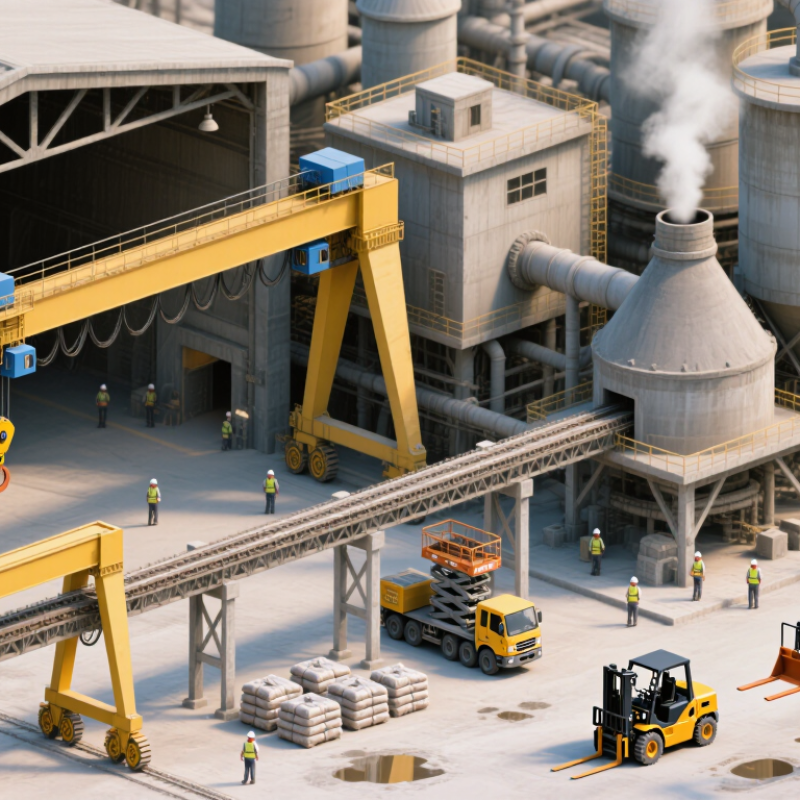
In cement plants, lifting equipment should be selected by duty, not capacity alone. ISO 4301-1 classifies cranes from M1 to M8 according to load spectrum and average operating time. Lower groups generally represent lighter or less frequent service; higher groups indicate more demanding use. These groups are not product grades. A crane’s actual class depends on its working cycles and load history.
Consider a raw-meal silo maintenance lift beside a clinker cooler crane working repeated shifts. The second may face more frequent cycles, heat, and abrasive dust, but site records should confirm the duty group. IEA’s 2023 cement-sector analysis reports that cement production contributes about 7% of global CO2 emissions. That figure does not determine crane class, yet it underscores why avoidable downtime matters. A tidy estimate can still miss real operating peaks.
Tips: Log lifted loads and cycles across representative shifts. Include start-stop frequency and harsh conditions in the review. Then check the applicable ISO tables with a qualified lifting engineer. Small details matter. Reassess after process changes, too.
Capacities and duty groups below are preliminary selection guides, not equipment ratings or a final ISO 4301 classification. The M1–M8 group applies to crane mechanisms; the appropriate group depends on the actual load spectrum, operating time, and mechanism design.
| # | Lifting equipment option | Typical cement-plant use | Indicative capacity range | Preliminary mechanism duty group | Selection considerations |
|---|---|---|---|---|---|
| 1 | Overhead bridge crane | Kiln, mill, and crusher maintenance; lifting motors, gearboxes, and machine components inside workshops. | 5–100 t | M3–M7, depending on utilization and load spectrum | Check runway capacity, hook coverage, headroom, lifting height, and whether tandem lifting is required. |
| 2 | Gantry crane | Outdoor maintenance areas, equipment laydown yards, and locations without building-supported crane runways. | 5–50 t | M3–M6, depending on service intensity | Account for wind, outdoor corrosion, ground-bearing pressure, travel path, and power supply. |
| 3 | Jib crane | Localized lifting at workshop benches, pump stations, and equipment service points. | 0.25–5 t | M2–M5, depending on cycle frequency | Verify column or wall strength, working radius, rotation limits, and clearance from nearby equipment. |
| 4 | Monorail hoist system | Repeatable movement of components along a defined route, such as between maintenance or process access points. | 0.5–10 t | M3–M6, depending on travel and lifting cycles | Confirm supporting-structure loads, curve and switch geometry, trolley travel, and access for inspection. |
| 5 | Electric wire-rope hoist | Powered lifting on bridge cranes, gantry cranes, and monorail systems handling heavier maintenance loads. | 0.5–50 t | M3–M7, selected for the calculated mechanism duty | Review starts per hour, operating time, reeving, lifting speed, brake arrangement, and service environment. |
| 6 | Electric chain hoist | Lighter maintenance lifts at workshops, inspection platforms, and equipment access points. | 0.125–5 t | M2–M5, subject to actual operating conditions | Consider chain-container clearance, suspension type, duty cycle, dust protection, and maintenance access. |
| 7 | Manual chain block | Occasional low-frequency lifts for inspection and repair where powered lifting is unnecessary or unavailable. | 0.5–10 t | Determine from the applicable equipment standard and service conditions; do not assume an M group from capacity alone. | Provide a verified anchor point; inspect hooks, load chain, and operation before use. |
| 8 | Electric lifting winch | Controlled pulling or lifting for maintenance tasks, provided the installation is designed for the intended load direction. | 0.5–20 t line pull | M2–M6, where the mechanism is classified under the applicable crane design basis | Check anchorage, rope fleet angle, drum capacity, line pull, braking, and whether the task involves lifting or pulling. |
| 9 | Mobile crane | Temporary lifts in open plant areas, including delivery, installation, and replacement of large components. | 20–250 t, depending on configuration and radius | Classify relevant mechanisms from manufacturer data and the selected standard; a single M group cannot be inferred for the whole crane. | Use the load chart for the exact setup; assess outrigger support, ground conditions, access, and overhead hazards. |
| 10 | Hydraulic gantry or strand-jack system | Special heavy lifts or controlled positioning of major components during planned shutdowns and installation projects. | Project-specific; commonly engineered for loads from tens to hundreds of tonnes or more | Project-specific; confirm the applicable classification method with the system designer | Require an engineered lift plan, verified load paths, synchronized operation, stability checks, and defined hold points. |
Duty-group note: M1–M8 are mechanism classification groups, not universal labels assigned solely by equipment type or rated capacity. Confirm the governing ISO 4301 edition, load spectrum, operating hours, lifting cycles, and component-level requirements during engineering design.






 Ms.Lily International Sales Director
 Join 3S Group