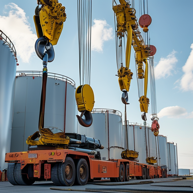
An LNG tank hoist is a specialized lifting system for moving liquefied natural gas storage tanks and related equipment. The term “Lng Tanks Hoist” is often used in project documents, although technical wording may vary between manufacturers. These systems support controlled lifting during fabrication, installation, inspection, and maintenance. They are not ordinary workshop cranes.
The hoist usually combines a steel frame, lifting beam, wire ropes or chains, drive components, brakes, and certified attachment points. Operators use these parts to raise a tank gradually and keep it balanced. A typical lift may involve a large cylindrical vessel, cold-weather insulation, and narrow clearances around support saddles. Small alignment errors can damage nozzles, insulation, or foundation connections. It looks simple. It is not.
Before lifting, qualified personnel confirm the tank’s weight, center of gravity, lifting-lug condition, rated capacity, and travel path. Load charts and manufacturer instructions should guide the setup. Inspection records also matter, especially for hooks, slings, brakes, limit switches, and emergency stops. Experienced teams watch for uneven loading, sudden movement, wind, and contact with nearby structures. The hoist does not make a difficult lift automatically safe. Site procedures, competent supervision, and clear communication remain essential. Some terminology and designs differ, so readers should verify details against the actual equipment documentation. That limitation deserves attention. This guide explains how an LNG tank hoist works, what its main components do, and why careful planning protects both the vessel and the people nearby.
An LNG tank hoist is a specialized lifting device used to raise, lower, and position equipment around liquefied natural gas storage tanks. It may handle pumps, valves, inspection tools, or removable access covers. Unlike a general workshop crane, it must operate near cryogenic systems, restricted spaces, and potentially hazardous vapors. Its frame, wire rope, chain, motor, brake, and control unit are selected for controlled movement and reliable load holding.
During operation, the hoist converts motor power into vertical motion through a drum, sheave, or geared lifting mechanism. Operators use pendant controls or remote systems to move the load slowly. Limit switches stop overtravel. Load indicators help prevent excessive force. Guide rails can reduce swinging, especially when equipment passes through a narrow tank opening. The equipment is usually installed above the tank or on a service platform, keeping sensitive drive components away from the coldest areas.
The International Gas Union’s 2024 World LNG Report recorded global LNG trade at about 404.3 million tonnes in 2023. This scale increases demand for dependable maintenance equipment. The International Energy Agency’s Gas 2024 report also identified continuing LNG supply growth as a major market trend. Yet, field conditions remain unpredictable. Ice, poor visibility, vibration, or a slightly misjudged load can affect a lift. A hoist may meet its rated capacity, but that does not guarantee safe handling. Engineers still need inspection records, temperature checks, emergency stops, and trained judgment before every lift.
This representative chart shows how the gross lifting load increases as a cryogenic LNG tank is filled. The calculation assumes a tank tare mass of 8 metric tonnes and an LNG density of approximately 450 kg/m³, a commonly used engineering value within the typical LNG density range. A tank hoist lifts the vessel using rated lifting points, while the hoist, rigging, brakes, and support structure must all be selected for the maximum gross load plus appropriate safety margins.
What Is an LNG Tank Hoist and How Does It Work?
An LNG tank hoist is a lifting system designed to move cryogenic storage tanks safely. These tanks are heavy, insulated, and sensitive to impact. The main frame supports the lifting load and keeps the equipment aligned during movement. A reinforced lifting beam spreads force across approved lifting points. This reduces stress on the tank shell and insulation.
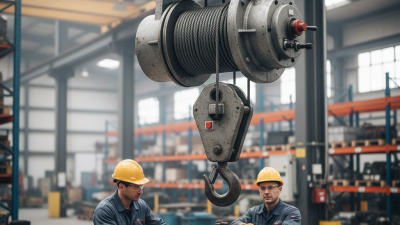
The hoist motor provides controlled vertical movement through a gearbox, drum, and wire ropes or chains. Mechanical brakes hold the tank when power stops. Guide rollers limit swinging, while load cells monitor weight and uneven loading. A control panel manages speed, direction, and stopping distance. Emergency stop switches must remain easy to reach. Keep it steady.
Experienced technicians inspect ropes, hooks, shackles, brakes, and limit switches before each lift. A hook latch helps prevent accidental release. Sensors can stop travel when the tank reaches a defined height or position. However, sensors do not replace human judgment. Small errors matter. Uneven ground, wind, or a poorly centered load can change the lifting behavior quickly. In practice, drawings rarely show every handling difficulty, especially around tight access areas. That is why operators should verify clearances, communication signals, and equipment condition on site. A well-designed hoist may appear simple, but each component carries a specific safety responsibility.
| Component or Data Dimension | Typical Data or Specification | Primary Function | How It Works in LNG Tank Service | Key Design and Safety Considerations |
|---|---|---|---|---|
| LNG Tank Hoist | Mechanical lifting equipment used for maintenance, inspection, or component handling around LNG storage facilities | Raises, lowers, and positions maintenance loads | An electric, pneumatic, or manual drive turns a lifting drum, wheel, or chain mechanism. The lifting element transfers the force to the suspended load. | The hoist must be selected according to rated load, lifting height, duty cycle, travel arrangement, environmental conditions, and applicable lifting regulations. |
| LNG Operating Temperature | Liquefied natural gas is commonly stored near −162°C at approximately atmospheric pressure | Defines the cryogenic environment that may affect nearby materials and equipment | The hoist is normally positioned outside the primary cryogenic containment area, while its supports, attachments, or lifting accessories may be exposed to cold surfaces or vapor zones. | Materials, seals, lubricants, insulation, and clearances must be suitable for the actual temperature exposure. The hoist should not be assumed to be cryogenic-rated unless specifically designed and certified for it. |
| Electric Motor or Drive Unit | Motor-driven systems commonly use low-voltage or medium-voltage industrial power according to the installation design | Provides the torque required to lift or lower the load | Electrical energy is converted into rotational motion. The drive may include variable-speed control for smoother starting, stopping, and positioning. | Motor protection, enclosure rating, thermal protection, grounding, and hazardous-area classification must match the site risk assessment. |
| Gearbox or Reduction Mechanism | Reduces motor speed and increases output torque | Allows the motor to lift a heavy load at a controlled speed | The gearbox transmits power through gears to the drum, chain wheel, or lifting shaft. A reduction ratio is selected based on load and required lifting speed. | Gear lubrication, alignment, temperature rise, vibration, and maintenance access are important for reliable operation. |
| Wire Rope or Load Chain | Load-bearing element selected for the hoist’s rated capacity and lifting height | Transfers lifting force between the hoist and the load | A wire rope winds onto a drum or passes over sheaves. A chain engages with a pocket wheel or chain sprocket and is collected in a chain container. | Inspect for broken wires, corrosion, kinks, deformation, elongation, wear, and improper reeving. The working load limit must not be exceeded. |
| Drum, Sheaves, or Load Wheel | Rotating lifting elements matched to the rope or chain size | Stores, guides, or redirects the lifting element | The drum winds the rope, while sheaves change the direction of the rope and may provide mechanical advantage in multi-fall arrangements. | Correct diameter-to-rope ratio, groove condition, fleet angle, guarding, and alignment help prevent accelerated wear. |
| Mechanical Holding Brake | Fail-safe brake that engages when power is removed or a stop command is issued | Holds the suspended load and controls stopping | In a spring-applied, electrically released design, springs apply the brake when power is lost, helping prevent unintended load descent. | Brake capacity, lining wear, stopping distance, heat dissipation, and inspection intervals must be established by the equipment design and maintenance program. |
| Trolley or Traveling Mechanism | Optional mechanism for horizontal movement along a beam, rail, or monorail | Moves the hoist and suspended load to different service locations | Powered wheels or a push/pull arrangement travel along the supporting track while the hoist performs vertical lifting. | Track alignment, wheel loading, end stops, travel limits, impact protection, and structural load capacity must be verified. |
| Support Beam, Monorail, or Tank-Mounted Structure | Structural member designed for the hoist’s maximum imposed loads | Transmits vertical and horizontal forces to the supporting structure | The support carries the hoist, load, dynamic effects, and possible side loads during movement or positioning. | Structural calculations should consider rated load, impact factors, fatigue, wind, seismic effects where applicable, corrosion allowance, and connection details. |
| Upper and Lower Limit Devices | Position-sensing devices that define safe lifting boundaries | Help prevent over-travel and mechanical damage | When the hook block or lifting element reaches a preset limit, the control system interrupts the relevant direction of motion. | Limit devices are protective controls, not substitutes for operator attention, load control, or the mechanical brake. They require periodic functional testing. |
| Overload Protection | Load-limiting device, torque limiter, or electronic load monitoring system | Reduces the risk of lifting beyond the rated capacity | The system detects excessive force or motor torque and prevents continued lifting when a preset limit is reached. | Overload protection should be calibrated, tested, and protected from bypassing. It does not correct unstable loads or poor rigging practices. |
| Control Station and Pendant | Wired pendant, local push-button station, or remote control | Controls hoist, lowering, travel, and emergency stop functions | The operator sends commands to contactors, motor controllers, brakes, and travel drives through the control circuit. | Controls should be clearly labeled, protected against accidental operation, and arranged so the operator has a safe view of the load and travel path. |
| Emergency Stop System | Manual emergency-stop device that removes motion command and initiates a safe stop | Stops hazardous movement during an abnormal event | Activating the emergency stop interrupts the control circuit and normally causes the brake to engage according to the system design. | Emergency stops should be accessible, clearly identified, regularly tested, and reset only after the hazard has been assessed. |
| Grounding and Bonding | Electrical protective connection between conductive equipment and the site grounding system | Provides a path for fault current and helps control static electrical potential | Metallic hoist components and supporting structures are bonded where required by the electrical design and site procedures. | Grounding continuity, cable condition, connection integrity, and compatibility with hazardous-area requirements must be checked by qualified personnel. |
| Lifting Accessories | Slings, shackles, hooks, spreader beams, lifting points, and load-positioning devices | Connect the hoist to the load and distribute lifting forces | Accessories form the load path between the hook and the item being handled, such as valves, instruments, covers, or maintenance components. | Each accessory must have a visible working load limit and be inspected for wear, deformation, cracking, corrosion, and correct configuration before use. |
| Typical Operating Workflow | Inspect → rig → test lift → raise/lower → position → secure → unrig | Provides a controlled sequence for safe material handling | The operator verifies the equipment, attaches the load, performs a short test lift, moves at controlled speed, and lowers the load onto a stable support. | Loads should remain within the rated capacity, personnel should stay clear of suspended loads, and site-specific LNG work permits and exclusion zones should be followed. |
| Maintenance and Inspection Data | Inspection frequency depends on duty, environment, usage, manufacturer instructions, and applicable regulations | Maintains reliability and identifies deterioration before failure | Inspections typically cover brakes, hooks, ropes or chains, limit devices, controls, fasteners, structure, lubrication, and electrical protection. | Inspection records should document findings, defects, corrective actions, test results, and the date when the equipment is returned to service. |

Note: Actual hoist capacity, speed, lifting height, hazardous-area classification, structural loading, and cryogenic exposure limits must be determined from the project design, equipment documentation, risk assessment, and applicable regulations.
An LNG tank hoist is a specialized lifting system for moving cryogenic storage tanks safely during installation or maintenance. It combines a rated lifting frame, steel wire ropes or chains, synchronized motors, brakes, and control sensors. The equipment must match the tank’s weight, lifting points, and center of gravity.
The lift begins with a documented inspection. Technicians check the hoist, hooks, shackles, welds, and emergency stops. They confirm the ground is level and establish a clear exclusion zone. The tank is then connected to approved lifting points. Each connection is checked by hand and recorded. Small errors matter.
The operator raises the tank slowly, often only a few centimeters at first. This trial lift reveals uneven loading, rope movement, or unexpected tilting. If the tank stays balanced, the hoist continues upward at a controlled speed. Guide ropes help workers manage rotation without standing beneath the load. Sensors monitor travel limits and motor synchronization, although sensors should not replace direct observation. The tank moves horizontally or vertically into position, depending on the lifting layout. Workers then lower it gradually onto its supports, checking alignment at each stage. Once the load is stable, tension is released, and the rigging is removed. I would not treat a smooth lift as proof of a perfect process; temperature, wind, and small alignment changes can still expose weaknesses.
An LNG tank hoist lifts heavy equipment during tank installation, maintenance, or repositioning. Its safety depends on more than rated capacity. Every lift needs a verified load path, stable supports, and trained operators.
Before lifting, crews inspect wire ropes, hooks, pins, brakes, and structural connections. They confirm the load weight and check the center of gravity.
Keep clear. An exclusion zone prevents people from standing beneath suspended equipment.
Hoist controls should include emergency stops, upper and lower limit switches, and overload protection. Interlocks can prevent movement when guards are open or conditions are unsafe.
LNG areas require careful control of ignition risks. Electrical equipment should suit the classified area, with effective grounding and bonding. Gas detection, ventilation, and communication systems must remain available during the lift.
Operators should monitor alarms, wind, ice, and unexpected load movement. Weather matters too.
In practical work, a checklist can look complete and still miss a damaged connection or a confused hand signal. That weakness deserves attention, not blame.
Independent verification before energizing the hoist adds valuable protection. If a limit switch fails, stop the lift, isolate the equipment, and record the defect.
Reliable operation comes from disciplined controls, clear communication, and a willingness to question normal routines.
An LNG tank hoist is a lifting system designed to move heavy equipment around liquefied natural gas storage areas. It may handle valves, pumps, access covers, transfer hoses, and tank components during installation or servicing. In most facilities, the hoist operates above the work zone, using a chain, wire rope, hook, brake, and limit switches. It should not lift a filled or pressurized tank unless a qualified engineer approves the operation.
Common applications include LNG terminals, storage yards, fueling stations, and maintenance workshops. Technicians use hoists when removing a damaged valve or positioning equipment inside a narrow service area. Clear floor markings help control movement. Rated capacity must match the actual load, including slings and attachments. A few extra kilograms can matter. Weather exposure, vibration, and low temperatures may also affect performance.
Maintenance begins with a documented inspection schedule. Operators should check hooks for deformation, chains for stretched links, and wire ropes for broken strands. Brakes, controls, emergency stops, and limit switches require functional testing. Lubrication must follow the equipment specification, especially near cryogenic service. Bolts and mounting structures deserve close attention because looseness can develop gradually. Qualified personnel should perform periodic load testing and record every defect and repair. Paperwork may look complete, but site conditions often reveal missed details. That is why practical inspections should challenge the written plan.